
I love diagrams, but diagrams don’t wire cables for me. In this post I will show the physical mapping, the Proxmox bridge pattern I used, the OPNsense management model, and the first firewall policy I used to protect the lab. The network was already in place; below I explain what I did to build and secure it.
I saved complex topics, like Kubernetes and a full hardware-buy guide, for later posts. In this post I will focus on the steps I took to get the network working.
Here is the map for the setup:
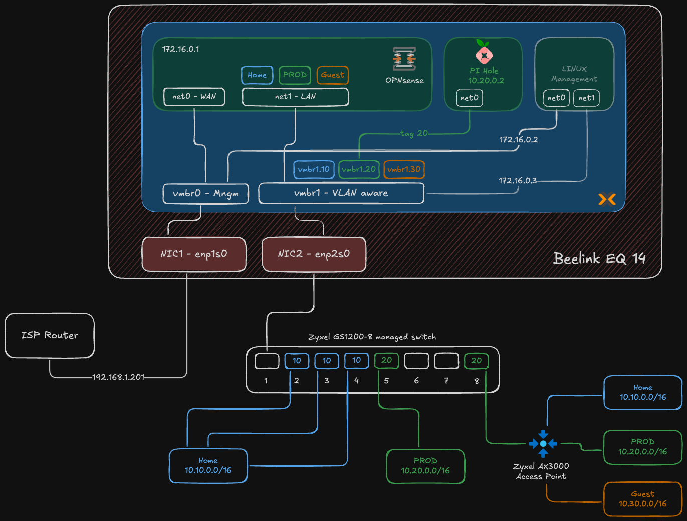
Figure: High-level segmented homelab network diagram showing physical NIC split, Proxmox bridges, VLANs, and OPNsense as the router-on-a-stick.
If you missed my earlier posts, here is a short summary:
- Why not a homelab? — why I decided to build a homelab and what I wanted to learn.
- From Enterprise to Homelab: Transforming My Home Network — the basic network plan I started with.
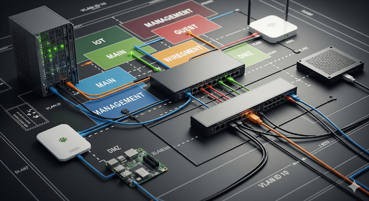
Hardware and Roles#
This wasn’t a shopping list. I used hardware I already had and assigned each piece a clear role. The approach was simple: set up the management/control plane first, create network boundaries with VLANs, then deploy applications.
| Component | Homelab Role | Proxmox VMs / Notes |
|---|---|---|
| Beelink EQ12 Mini PC (2 NICs) | Proxmox host (virtualization & network hub) | Hosts VMs: OPNsense (firewall/router), Pi‑hole (DNS), Linux management VM (bastion) |
| Zyxel GS1200-8 Switch | Layer-2 VLAN segmentation | Physical switch providing VLAN trunk to Proxmox and access ports |
| Zyxel AX3000 Access Point | Multi-SSID wireless mapped to VLANs | AP maps SSIDs to VLANs (HOME / PROD / GUEST) |
| Existing ISP router | Raw internet uplink (for now) | Placed in DMZ for staged migration; double NAT temporary |
The Build: a brief narrative#
Below I describe the decisions that shaped the build. The detailed, step-by-step work is in the “How I built the network” section… read that for the exact order and checks I ran.
I kept everything virtualized on the Beelink as a deliberate trade-off because it was the hardware I already had. Using a single host let me get a working foundation quickly and iterate safely… it’s a starting point. Later I plan to move OPNsense to bare metal for higher throughput and place Pi‑hole on a low‑power board (Orange Pi / Raspberry Pi) to reduce attack surface and power use.
The first hard boundary: physical and management networks#
Segmentation started with physical hardware and how I accessed it.
Physical separation: The Beelink mini PC has two physical network ports. One faces the untrusted internet; the other faces my trusted internal network.
- NIC 1 (
enp1s0) — WAN: Connects to the ISP router. - NIC 2 (
enp2s0) — LAN: Connects to the Zyxel managed switch and acts as the trunk for isolated VLANs.
- NIC 1 (
Proxmox host access: The Proxmox management interface lives on my existing ISP network at
192.168.1.201. I assigned this as a static address outside the ISP router’s DHCP pool to avoid address conflicts and keep host management predictable and separate from the virtual networks it serves.
Inside Proxmox, the physical split was mirrored by two virtual bridges.
vmbr0— WAN & host management bridge: Connected to the WAN port. The Proxmox host gets its management IP here. This bridge also provides the uplink for the OPNsense firewall VM.vmbr1— VLAN trunk: Connected to the LAN port, this bridge was the core of internal segmentation. By enabling the “VLAN aware” option, it became a virtual managed switch. I left this bridge unnumbered (no IP) to reduce the host’s attack surface and avoid accidental exposure. Proxmox moved VLAN-tagged frames; OPNsense handled routing and policy enforcement. In practice it acted as a traffic director:- It receives VLAN-tagged packets from VMs.
- It forwards that traffic out the physical LAN port to the Zyxel switch, preserving the VLAN tag.
- It lets a VM inside Proxmox communicate with a physical device on the same VLAN port on the switch.
How I built the network#
I built the network in clear, small steps so I could test and fix problems as I went. The order made the work predictable and reduced disruption to the house network.
Physical wiring and role split
- I connected the Beelink NIC1 to the ISP router for WAN and NIC2 to the Zyxel switch for LAN. That created a physical boundary between internet and internal traffic.
Install Proxmox and set management access
- I installed Proxmox on the Beelink and set a static management IP on the ISP side (
192.168.1.201) so I could manage the host without touching the virtual networks.
- I installed Proxmox on the Beelink and set a static management IP on the ISP side (
Proxmox network configuration
I created
vmbr0for WAN and assigned the Proxmox management IP.I created
vmbr1for the LAN trunk, enabled VLAN aware mode, and left it unnumbered (no IP) so the host had minimal exposure.
Physical NICs:
enp1s0is the WAN/management-facing NIC andenp2s0is the LAN-facing NIC that carries the VLAN trunk.vmbr0(MGMT + WAN): a Linux bridge bound toenp1s0with the host management IP192.168.1.201/24and the OPNsense WAN attached.vmbr1(LAN): a VLAN-aware bridge bound toenp2s0. It handles VLAN-tagged traffic and is intentionally left without an IP on the Proxmox host to reduce attack surface.VLAN sub-interfaces:
vmbr1.10(HOME),vmbr1.20(PROD),vmbr1.30(GUEST). Each maps to the VLAN IDs defined in OPNsense.How it works in practice: VMs can use VLAN-tagged interfaces or rely on OPNsense to terminate VLANs (router-on-a-stick). The bridge simply forwards tagged frames between VMs and the physical switch.
Why this layout: it keeps host management separate from VM networks, preserves clear physical boundaries, and centralizes routing/policy in OPNsense while using Proxmox as a simple L2 switch for VLANs.
Deploy OPNsense VM
- I created an OPNsense VM with two NICs: WAN on
vmbr0(access) and a LAN parent onvmbr1(trunk). - Inside OPNsense I created VLAN interfaces (10, 20, 30), assigned gateway IPs and DHCP ranges for each VLAN.
- I moved the OPNsense LAN off the ISP-assigned network and placed host and device management onto a dedicated management subnet
172.16.0.0/24. This keeps UIs and admin services reachable from a single, controlled network while preventing accidental exposure to general client VLANs. - I started with a deny-by-default firewall model. Each VLAN has its own interface and gateway, and I only created explicit allow rules for necessary traffic.
- I created an OPNsense VM with two NICs: WAN on
Deploy Pi-hole
- I deployed Pi-hole on VLAN 20 (PROD) with a static IP (
10.20.0.2). - DNS enforcement: I used DHCP to push Pi-hole as the only DNS server for clients, and then added firewall rules to block outbound DNS (port 53) to other resolvers so clients couldn’t bypass filtering.
- I deployed Pi-hole on VLAN 20 (PROD) with a static IP (
Deploy management VM
- I created a Linux management VM and gave it two virtual NICs. One NIC is bound to
vmbr0so the VM can access the internet for updates and outbound management tasks. The other NIC is bound tovmbr1(the VLAN-aware trunk) so the VM can reach the OPNsense LAN at172.16.0.1and the Zyxel switch at its management IP at172.16.0.3. - This split lets the management VM perform internet-facing tasks when needed while keeping device UIs and switch management on the isolated management subnet.
- I created a Linux management VM and gave it two virtual NICs. One NIC is bound to
Configure the Zyxel switch and access point
- I changed the Zyxel management IP to
172.16.0.3so the switch sits on the same management subnet as OPNsense and the management VM. - In the Zyxel GUI I created VLANs 10, 20, 30. I set the Proxmox port as a trunk (tagged for those VLANs), set the AP port as a trunk, and configured access ports with the correct PVIDs for Home and Prod devices. The Guest network is only WiFi.
- On the AP I mapped SSIDs to VLANs so wireless clients were placed on the right network.
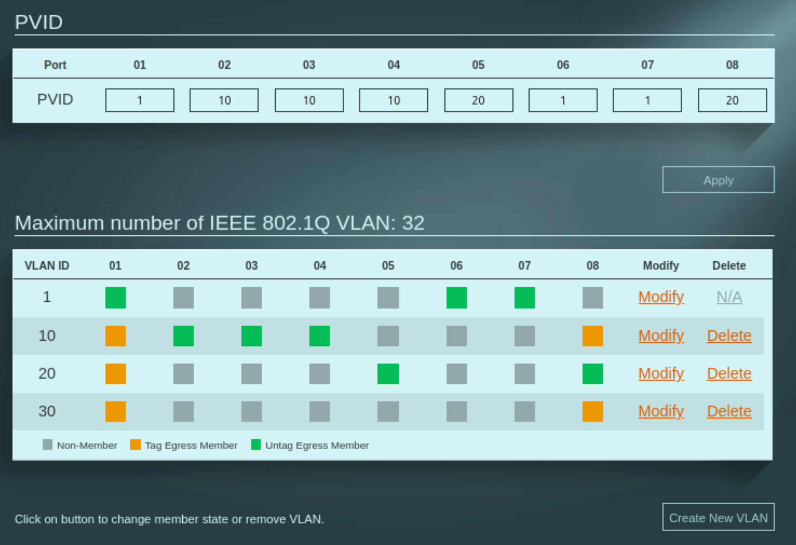
Figure: Zyxel GS1200-8 configuration.
- I changed the Zyxel management IP to
Firewall and DNS policy
- I set deny-by-default rules on all VLANs in OPNsense, then added explicit allow rules where needed.
- I forced clients to use Pi-hole for DNS via DHCP and blocked other DNS servers at the firewall so clients couldn’t bypass filtering.
Verify and iterate
- I tested client-to-gateway reachability, tested DNS against Pi-hole, and reviewed OPNsense logs for DHCP and DNS traffic.
- I fixed small issues (wrong PVID, missing VLAN tag on a VM NIC) and reran the checks.
- Quick verification checklist I used after each change:
- From the management VM, confirm OPNsense at
172.16.0.1is reachable and the Zyxel switch responds at its management IP (example172.16.0.3). - From a HOME VLAN client, ping the HOME gateway
10.10.0.1and verify DNS resolution is served by Pi-hole. - From a PROD VM, confirm access to Pi-hole at
10.20.0.2and verify inter-VLAN traffic is blocked by default. - Check OPNsense logs for DHCP leases and DNS queries to validate policy enforcement and correct client placement.
- From the management VM, confirm OPNsense at
This step-by-step approach let me find problems early and keep the family network working while I built the lab.
A note on the edge: embracing pragmatism with double NAT#
My ISP supplies a single device that acts as both a fiber modem and a router and doesn’t offer a true bridge mode. That places OPNsense behind the ISP device and creates a double NAT.
I accept this as a short-term, pragmatic compromise while I build and validate the firewall and VLANs. I don’t need any public-facing services now. If I need to expose something later I’ll use Cloudflare Tunnel to avoid inbound port configuration on the ISP device. When I’m ready for production I will request a standalone ONT from the ISP, remove their router from the path, and let OPNsense be the single edge gateway.
Description and implications — short version:
Impacts:
- Inbound complexity: port‑forwards must be configured on both the ISP device and OPNsense (or a DMZ/1:1 NAT used), which doubles configuration and troubleshooting points.
- NAT traversal: protocols like SIP or some peer-to-peer/remote‑access tools may fail or require TURN/STUN/VPN workarounds.
- Operational quirks: asymmetric routing, increased connection‑tracking load, and MTU/fragmentation issues can surface during testing.
Mitigations I used:
- Cloudflare Tunnel for any temporary public exposure: no inbound port opens, automatic TLS and auth, easy to test services.
- Use ISP DMZ/1:1 NAT for service passthrough during validation when needed.
Trade-offs:
- Tunnels are convenient but add an external dependency and a small latency penalty.
- For high-throughput or latency-sensitive services prefer a public IP or routed IPv6.
Blueprint made real#
The diagrams became wiring and configs. In short: I used Proxmox bridges to separate host/WAN and a VLAN‑aware LAN trunk, ran OPNsense as the central router/firewall with a deny‑by‑default posture, and placed core services (Pi‑hole, a management VM) on isolated subnets. The Zyxel switch and AP enforced VLAN boundaries at L2 and kept wireless SSIDs mapped to the correct networks.
Andrei